Experimental Determination of Layer Height of Granular Flow down Rough Inclined Surfaces
Rishabh Datta is a 4th Year Mechanical Engineering student at Georgia Tech, Atlanta. Rishabh is interested in Green Technology, Concentrated Solar Power, Renewable Energy, Data Science, and CFD. For more projects, click here.
Determining Height of Granular Flow using Optical Methods
Overview
The objective of this project is to experimentally determine the layer height h for granular flow of particles down rough inclined surfaces optically from images of the flow. Layer height h and critical layer thickness hstop are of significance to determine the flow line equation, and the velocity profile of the flow as shown in the following equations.
α and γ are experimentally determined fitting coefficients.
This project was completed at the Solar Fuels Laboratory, Georgia Tech, under the supervision of Dr. Peter Loutzenhiser.
Methodology
Particles used in this project were CAM-28 (Al Doped Calcium Manganate) which are expected to have a mean diameter of about 41 microns. These particles were flowed down a rough inclined surface at a known angle of inclination θ for which uniform flow was observed. Images of the flow were captured suing the FASTCAM SA-3 high speed camera positioned normal to the surface. A laser beam was positioned to shoot a cross-beam across the surface. The set-up is shown below.
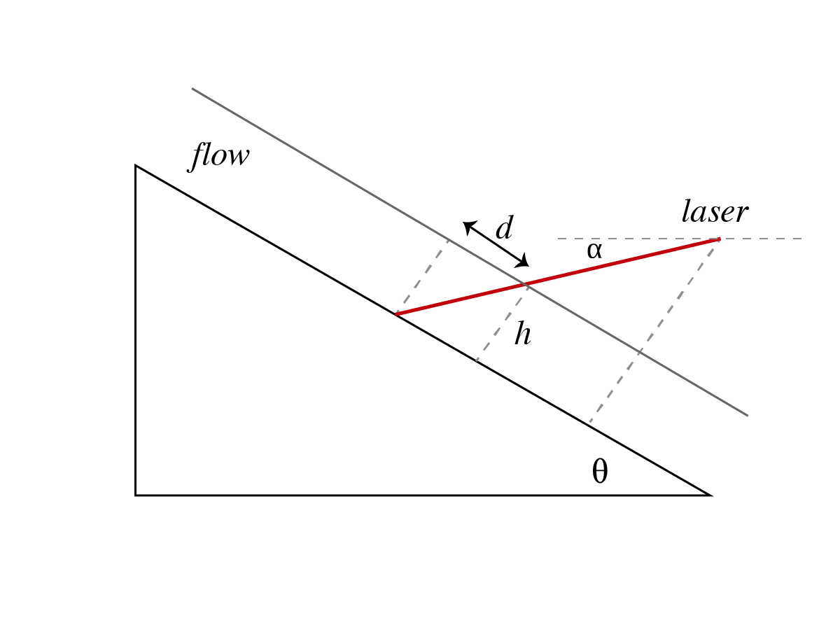
Figure 1: Experimental Set-Up
Layer height and critical layer thickness were measured optically from the displacement of the laser on the surface during flow using the following relationship.
Calibration
The calibration image as shown in Figure 2 consists of a checkerboard image of known dimensions taped to the surface. This image was used to perform persective correction and determine the scale using MATLAB's Image Processing Toolkit. As shown in Figure 2, the corners of the checkerboard were identified, and then transformed to ensure that the dimension of each individual square is identical in the transformed image.
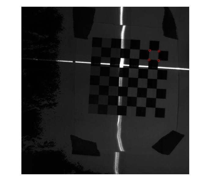
Figure 2: Calibration Image
The scale in mm/px is determined from the transformed calibration image as shown in Figure 3.
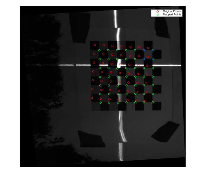
Figure 3: Transformed Calibration Image
Determination of Layer Height
The transformation obatined from the calibration was applied to the control image (image of surface before flow) and to the test images (images of surface during flow and after flow).A RANSAC algorithm was used to statistically fit a line to the laser beam. The average displacement was calculated from the deviation in the laser position between the test image and control image as shown in Figures 4 and 5.
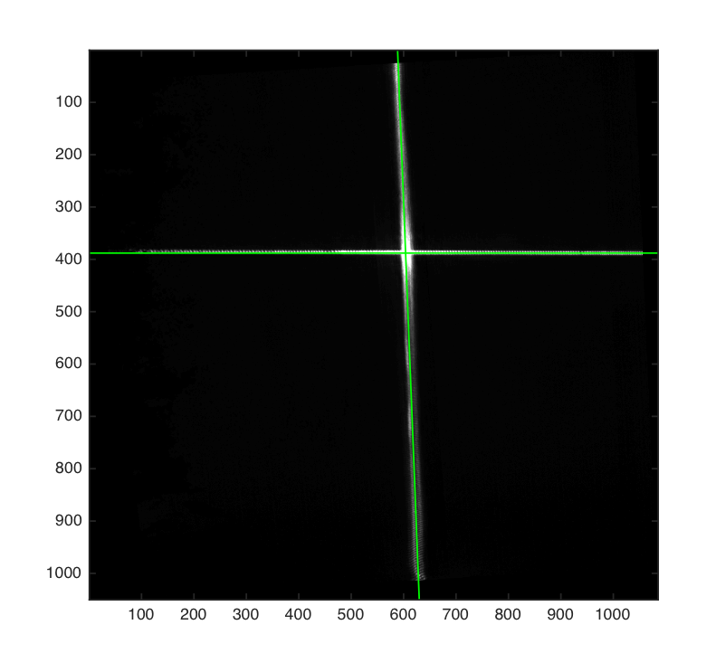
Figure 4: Fitting a curve to the laser beam on the transformed control image
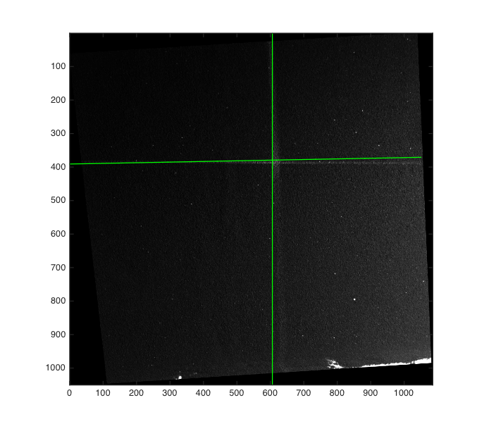
Figure 5: Fitting a curve to the laser beam on the transformed test image
Average values of layer height and critical layer thickness were then determined from the mean displacement of the laser beam using the geometric relationship between height and displacement.
Results
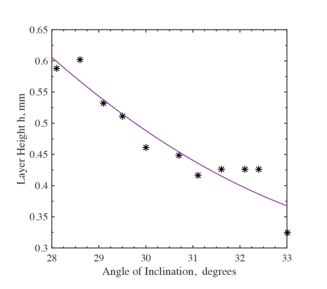
Figure 6: Variation of layer height with angle of inclination θ
Layer height was observed to decrease with an increase in angle of inclination. This is because for the same mass flow rate, the increase in average velocity (due to steeper slope) causes a decrease in the height of the flowing bed.
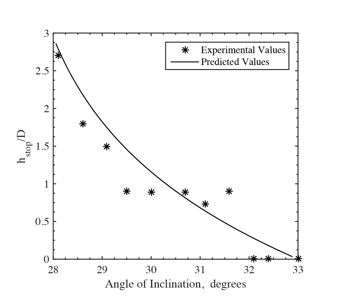
Figure 7: Variation of hstop with the angle of inclination θ
Figure 7 shows the variation of critical thickness with the angle of inclination, as well as the expected variation obtained from the flow line equation. The experimental values fit the model well for shallower angles, but demonstrate significant noise at steeper angles, for which the image processing method used to determine h and hstop was less accurate. The displacement of the laser was too small at higher inclinations where height was only a few layers of particles thcik.
Conclusions
The method used is more accurate to lower angles of inclination, for which the layer height of granular flow is larger. For steeper angles close to the upper threshold where uniform flow is observed, the method detects little displacement of the laser. This is an issue, especially for small particles like CAM-28. The error may be reduced by using a finer laser, or higher resolution on the camera. Nevertheless, the method does provide a viable alternative to using a more expensive laser displacement sensor.